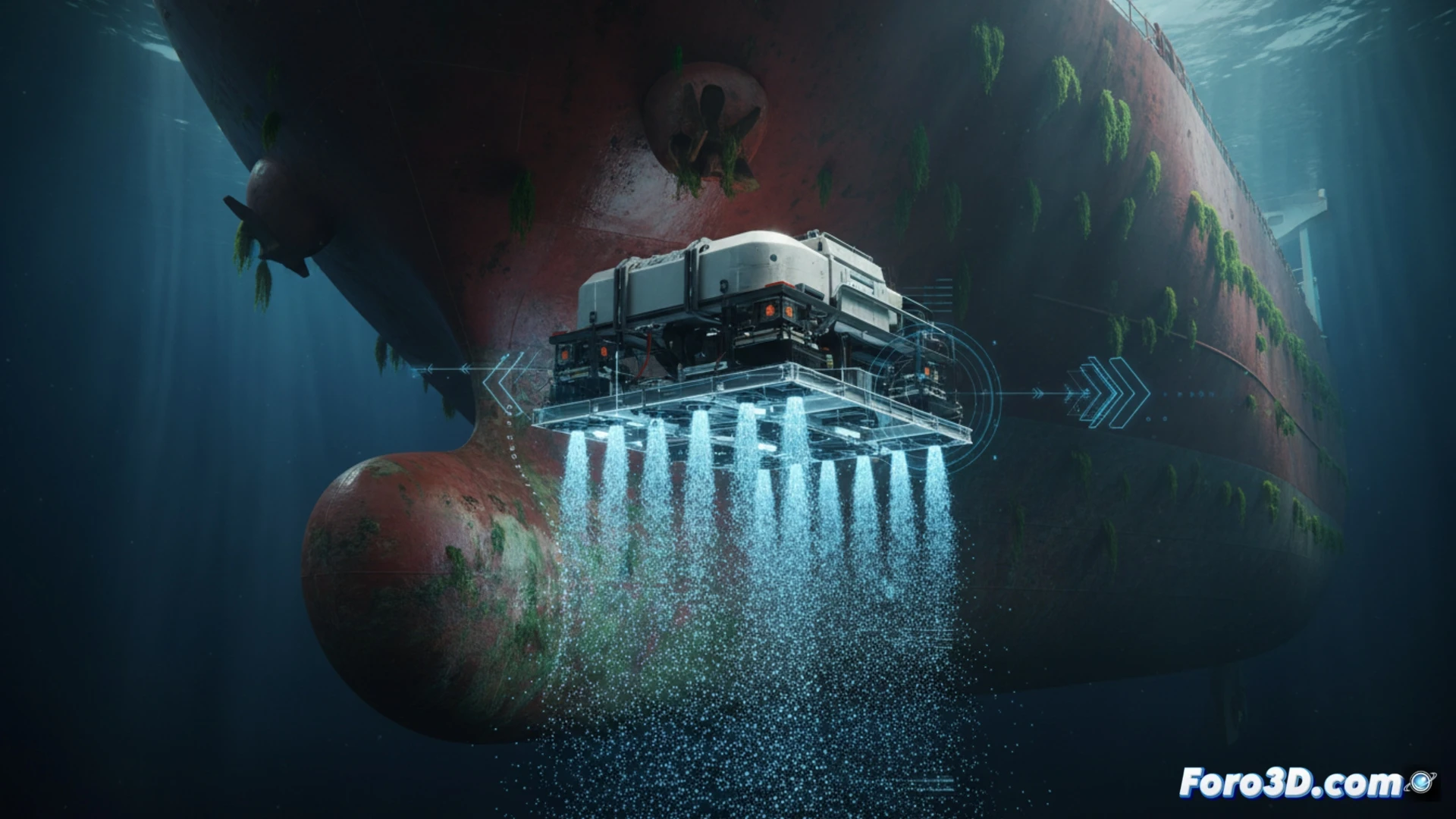
The HullWiper is a remotely operated underwater vehicle (ROV) designed to clean ship hulls using high-pressure water jets without damaging the anti-corrosive paint. Its 3D modeling requires capturing the hull geometry, jet nozzles, and fluid dynamics. This article breaks down the technical workflow for simulating its operation in virtual environments, optimizing fuel efficiency and the lifespan of the marine coating.
Technical Workflow: Scanning, Meshing, and Trajectory Simulation 🤖
The process begins with laser scanning of the ship's hull to generate a point cloud. This is converted into a high-resolution polygonal mesh in CAD software (such as Blender or Rhino). The HullWiper ROV model, designed with servomotors and adjustable nozzles, is then integrated. To simulate the water jets, dynamic particles or fluids based on the SPH (Smoothed Particle Hydrodynamics) method are used. The next step is to define cleaning trajectories using sweep algorithms, avoiding angles that could erode the paint. The final simulation validates the pressure and exposure time, adjusting parameters to not exceed the coating's adhesion limits.
Virtual Optimization: Efficiency and Paint Damage Prevention 🚢
3D simulation allows testing hundreds of configurations without real-world risks. By visualizing the pressure distribution on the hull, critical areas where the jet could lift the paint are identified. Adjusting the distance and angle of the nozzles in the model achieves uniform cleaning with 20% less operation time. This approach reduces the ship's fuel consumption by up to 10% and extends the coating's lifespan, demonstrating that underwater robotics and 3D modeling are indispensable allies in modern naval automation.
What CFD simulation parameters should be considered in the 3D modeling of the HullWiper ROV's water jets to optimize cleaning efficiency without damaging the ship's hull?
(PS: Simulating robots is fun, until they decide not to follow your orders.)