The trade of a mechanical fitter demands millimeter tolerances and a trained eye to detect deviations. 3D technology, through scanning and modeling, allows comparing real parts with their original CAD design in minutes. A clear example: when adjusting a cylinder head gasket, a 3D scanner detects deformations of 0.1 mm that would go unnoticed to the naked eye, saving hours of grinding.
Digital tools for fine work 🔧
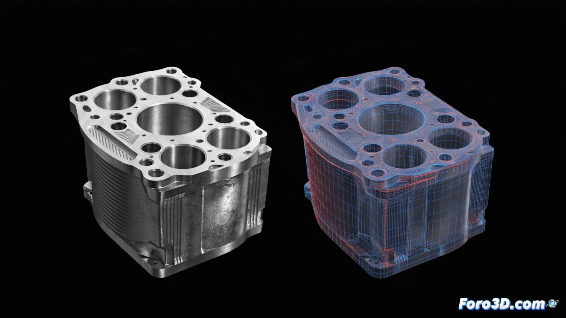
To apply this technology, you need a handheld 3D scanner like the EinScan H or the Artec Leo, capable of capturing complex geometries in seconds. The key software is Geomagic Control X for deviation analysis and SolidWorks or Fusion 360 to modify models. The workflow is simple: scan the part, import the STL file into the inspection software, and overlay the original design. The differences appear in a color map indicating red zones (excess material) or blue zones (lack of material). With this, the fitter decides where to sand, mill, or add material without guesswork.
The day the scanner told me I was right 📐
I remember a veteran fitter who, after hours calibrating a gear, felt a strange vibration. His instinct told him the problem was the shaft, but the blueprint said otherwise. He borrowed a 3D scanner, ran it over the part, and the software showed a 0.15 mm deviation on the shaft. His boss, who blindly trusted the blueprint, had to accept the digital evidence. Since then, the fitter brings the scanner to work and jokes: Now even the boss believes in my hunches, as long as they come with a point cloud.