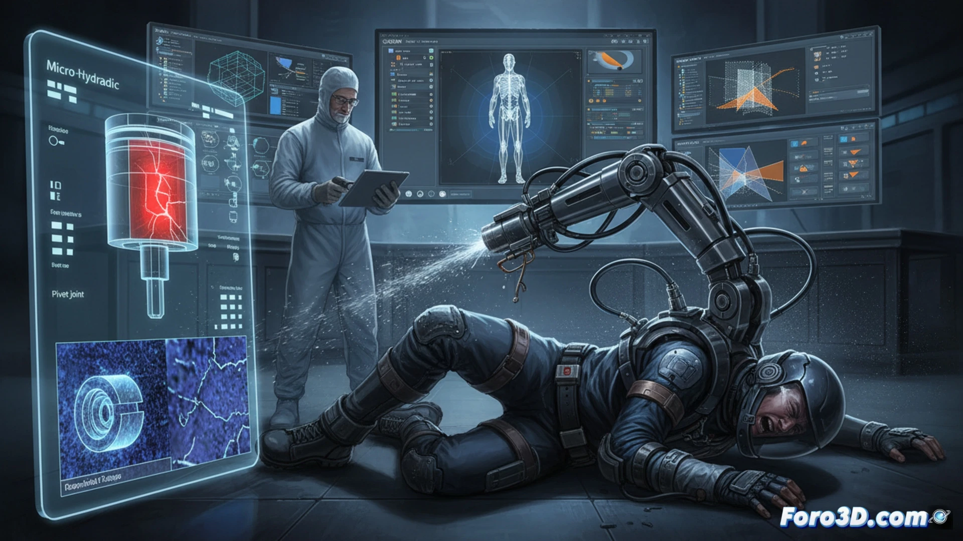
A worker suffered serious injuries when a hydraulic logistics assistance exoskeleton executed a violent reverse movement without warning. The investigation focuses on determining whether the cause was a software error or material fatigue. To this end, a workflow of 3D metrology and mechanical simulation has been implemented to analyze sub-millimeter deformations in the pistons and wear at the pivot points of the structure.
Technical Workflow: Metrology and Stress Simulation 🔧
The process begins with sub-millimeter scanning of the damaged exoskeleton. Using GOM Inspect, metrology of the micro-hydraulic pistons is performed to detect plastic deformations or microcracks. In parallel, CloudCompare is used to compare the meshes of the healthy component (original CAD file) against the deformed part, generating a chromatic deviation map. This analysis reveals stress concentration zones at the pivot points. Subsequently, these real geometries are imported into SolidWorks to execute a finite element analysis (FEA) that simulates accumulated cyclic loads, determining whether the material exceeded its fatigue limit before collapse.
Reconstruction and Diagnosis: Between Code and Metal 🛠️
The reconstructive animation of the failure, created in Blender, integrates deformation data with the exoskeleton's kinematics. This allows visualizing the exact sequence of the violent reverse movement. The analysis concludes that, although the software may have sent an erroneous command, the catastrophic fracture was precipitated by material fatigue in the pivot supports, which exhibited accumulated wear not detectable in previous visual inspections. The combination of metrology and simulation has been key to ruling out a purely logical failure.
Would you validate with destructive testing?