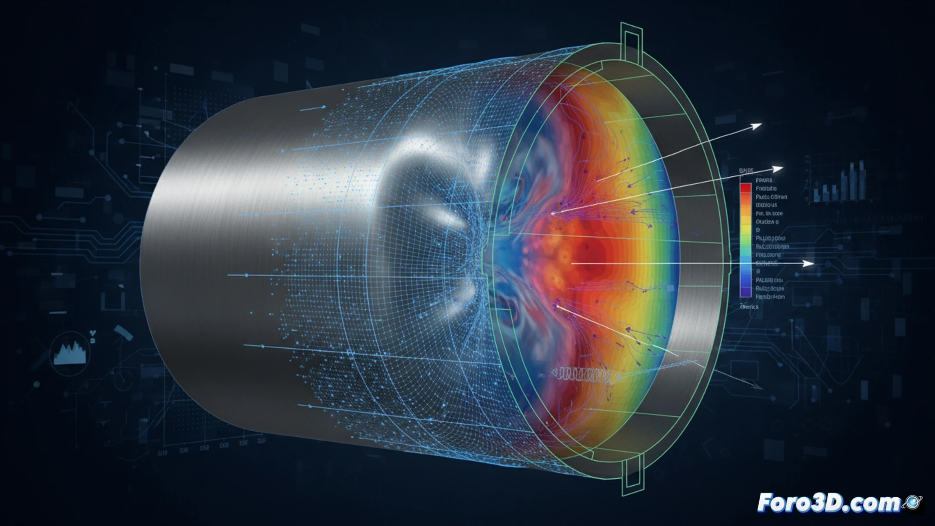
Forensic analysis of a steel tank for compressed air energy storage (CAES) revealed an anomalous bulge on its surface. The main hypothesis points to plastic deformation induced by an excessive thermal loading cycle during a rapid compression phase. To confirm this, a dual workflow is implemented: comparative 3D scanning with Geomagic Control X and finite element simulation with ANSYS Mechanical, allowing differentiation between recoverable elastic deformation and permanent material damage.
Forensic workflow: from point cloud to fatigue model 🔍
The process begins with capturing the actual tank geometry using a Leica Cyclone scanner, generating a high-density point cloud. This is imported into Geomagic Control X to perform a surface deviation analysis against the nominal CAD model. Areas with deviations exceeding 0.5% of the wall thickness are identified as candidates for plastic deformation. Subsequently, the mesh of the deformed area is extracted and transferred to ANSYS Mechanical. There, the boundary conditions of the real thermal cycle (temperature gradient and internal pressure) are applied to simulate the steel's behavior under the ASME BPVC fatigue standard. The simulation calculates Von Mises equivalent stresses and accumulated plastic strains, contrasting the results with the actual scan measurements to validate the hypothesis.
Thermal fatigue and asset reuse ⚙️
The correlation between the measured bulge and the simulated plastic strain field confirms that the steel exceeded its yield limit during the rapid compression cycle. This finding rules out tank reuse without annealing treatment or direct replacement, as thermal fatigue has reduced its residual service life. The integration of 3D scanning and FEM simulation not only diagnoses the failure but establishes a predictive inspection protocol for future load cycles in CAES systems.
How can the integration of 3D scanning and FEM simulation reveal the exact sequence of plastic deformation events that led to the anomalous bulge in a steel CAES tank?
(PS: Material fatigue is like yours after 10 hours of simulation.)