When Mechanical Precision Meets 3D Design
Fernando Alonso's recent retirement from the Italian Grand Prix due to a suspension failure is a brutal reminder of the importance of every component in a Formula 1 single-seater. 🏎️ In the world of 3D design, a similar error would be having a poorly configured bone hierarchy that ruins an entire animation. Recreating a suspension system in Rhino is not just a technical exercise; it is a way to understand the millimeter precision demanded by top-tier motorsport.
The Foundations of the Model: Reference and Organization
The first step to successful modeling is preparation. In a new Rhino file, units are set to metric and organized layers are created for each element: chassis, wheel, suspension, and auxiliaries. Importing or drawing the plan and elevation views of the car and wheel provides essential references to maintain dimensional cohesion. 📐 Locking basic volumes (bounding boxes) for key anchor points helps visualize the workspace and avoids positioning errors later on.
- Organization by layers: Clear structuring of the model components.
- Reference geometry: Use of planes and dimensions to guide modeling.
- Definition of critical points: Establishment of pivot centers and anchors.
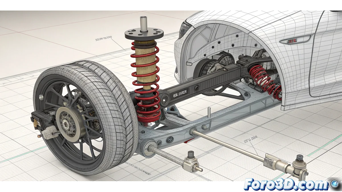
Shaping the Arms and Ball Joints
The creation of the suspension arms begins with the design of cross-sections using closed curves. These sections are arranged in planes perpendicular to the arm's length. 🛠️ Using commands like Sweep1 or Loft, the main surface of the arm is generated, to which FilletEdge is then applied to smooth critical joints. For the ball joints, cylinders are started and modified with boolean operations (BooleanDifference) to create pin housings, simulating the real functionality of the assembly.
Precision in NURBS modeling is not a luxury; it is the difference between a component that works and one that fails on the fastest curve.
Parametrization and Final Adjustments
To give flexibility to the design, Grasshopper becomes the perfect ally. By passing the reference curves to this environment, parameters such as lengths and radii can be controlled with sliders, allowing iteration and optimization of the design without having to redo the geometry manually. 🔧 For components like the spring, a Helix is used with the appropriate pitch and number of turns, to which a sweep with a circular profile is applied. The shock absorber is modeled as concentric cylinders, adding details with booleans and chamfers.
The Moment of Truth: Assembly and Verification
Once all the parts are modeled, their assembly proceeds using tools like Move, Rotate, and Orient3Pt. It is crucial to verify that there are no interferences between components, using sections or commands like Intersect. ✅ Simulating the full suspension travel by moving the wheel and the upright ensures that the spring and shock absorber do not collide at any point in the motion, avoiding the failure that took Alonso out of the race.
The Irony of Perfect Design
You finish the model, look at it proudly in the viewport, and think the render will be impeccable... until you remember that you didn't check the real spring travel with the car's dimensions. 😅 It is the digital equivalent of designing an F1 engine and realizing you used a shelf screw. Luckily, in forums like this, there is always a kind soul with a Grasshopper script that gets you out of trouble at the last moment. 🫠 At least our model won't break in Monza.