A Prior 3D Model Eliminates Blind Spots in Security
Planning an effective surveillance system no longer relies on assumptions. Experts now build a digital twin of the real space using 3D scanning technologies. This model becomes the ultimate testing ground to design, test, and refine every component before physical installation, eliminating human error. 🎯
Creating the Digital Base with Millimeter Precision
The first step is to capture reality. A laser scanner, such as the Leica RTC360, records the complete geometry of an environment, for example, a museum. This device generates an extremely dense and precise point cloud. Technicians then process this data in specialized software, such as Autodesk ReCap, to generate a solid, ready-to-use 3D model. This virtual replica contains every column, display case, and hallway with exact accuracy.
Key Advantages of Initial Scanning:- Absolute precision: Dimensions and obstacles are captured without margin for error.
- Complete documentation: A permanent 3D record of the site's condition is obtained.
- Basis for simulations: The model is the environment where the entire system will be tested.
The real thief in security is the assumption that placing cameras randomly works. 3D simulation leaves no room for improvisation.
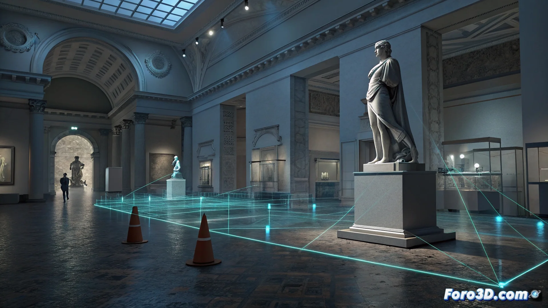
Simulate and Analyze Coverage in the 3D Engine
With the 3D model loaded into an engine like Unreal Engine or Unity, the active design phase begins. Planners place virtual surveillance cameras in the proposed locations. They configure real technical parameters: focal length, resolution, tilt angle, and field of view. The software renders the perspective of each camera, automatically calculating the covered zones and, critically, the shadows and obstructions created by the environment's objects. This reveals corridors or corners where a person could move without being detected: the blind spots.
Parameters Simulated:- Field of view (FOV) and effective range of each camera.
- Effect of architectural obstacles and furniture.
- Interaction of ambient lighting with camera vision.
Optimize the Design and Validate the Installation
Identifying blind spots allows immediate design iteration. Technicians adjust positions, change lens types, or add additional devices directly in the model. Tools like the JVSG IP Video System Design Tool help refine this technical process. The ultimate goal is to achieve overlapping coverage, where one camera's visual field covers another's blind area. Only when the simulation validates total coverage without gaps is the plan approved for physical system installation. This method saves time, reduces costs from rework, and ensures the system will work as designed from day one. ✅