The airbag, designed to save lives in milliseconds, can become a lethal projectile if its inflation mechanism fails. The recent news about a false inflation forces us to review the engineering behind these systems. From a 3D modeling perspective, we will analyze the activation sequence, from the impact sensor to the chemical inflator, to identify the exact point where gas pressure fails and deployment time deviates from the safety curve.
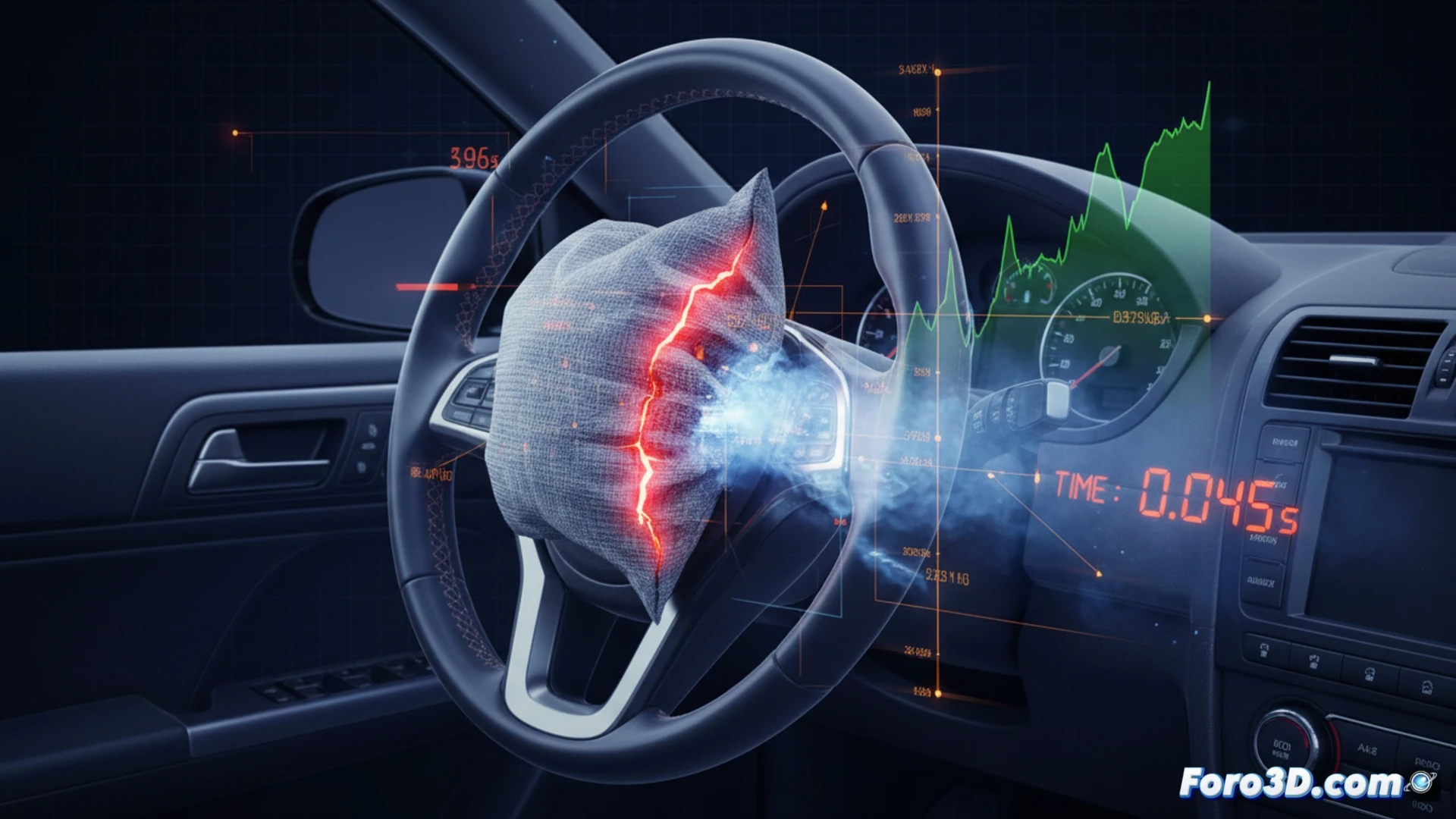
3D simulation of the activation sequence and failure point 🚗
To visualize the failure, we have modeled a sectioned airbag module in SolidWorks. The 3D diagram reveals three key components: the piezoelectric sensor, the sodium azide inflator, and the electronic control unit (ECU). In the correct simulation, the ECU receives the sensor signal at 5 ms, activating the inflator which generates nitrogen at 250 bar. In the faulty simulation, the model shows a signal latency of 15 ms or incomplete combustion of the chemical propellant. This produces a pressure of only 80 bar, insufficient to deploy the bag in time. The 3D animation contrasts both trajectories: an ideal pressure curve against a flat plateau indicating false inflation.
Design lessons to avoid false inflation 🔧
The model reveals that the failure lies not in the bag, but in the integrity of the sensor-inflator chain. A poorly calibrated sensor or an inflator with chemical impurities generates insufficient pressure. The technical solution involves redesigning the inflator housing with tighter tolerances and adding a backup pressure sensor inside the module. In 3D modeling, this translates to including a dual combustion chamber and a pressure verification channel before final ignition. Safety allows no shortcuts in simulation.
How can 3D modeling predict and visualize the trajectories of metallic fragments generated by a catastrophic airbag inflator failure to improve automotive safety standards?
(PS: ADAS systems are like in-laws: always watching what you do)