A cryonics center detected an anomalous temperature increase in its cryocoffins. The initial investigation pointed to a vacuum system failure, but 3D thermal mapping revealed the true cause: microfractures in the aerogel panels. Low-frequency vibrations, originating from a nearby construction site, had caused fatigue in the composite material, compromising the insulation. This case demonstrates that forensic analysis with 3D scanners is critical for sensitive infrastructure.
Technical Workflow: From Point Cloud to Fatigue Simulation 🔬
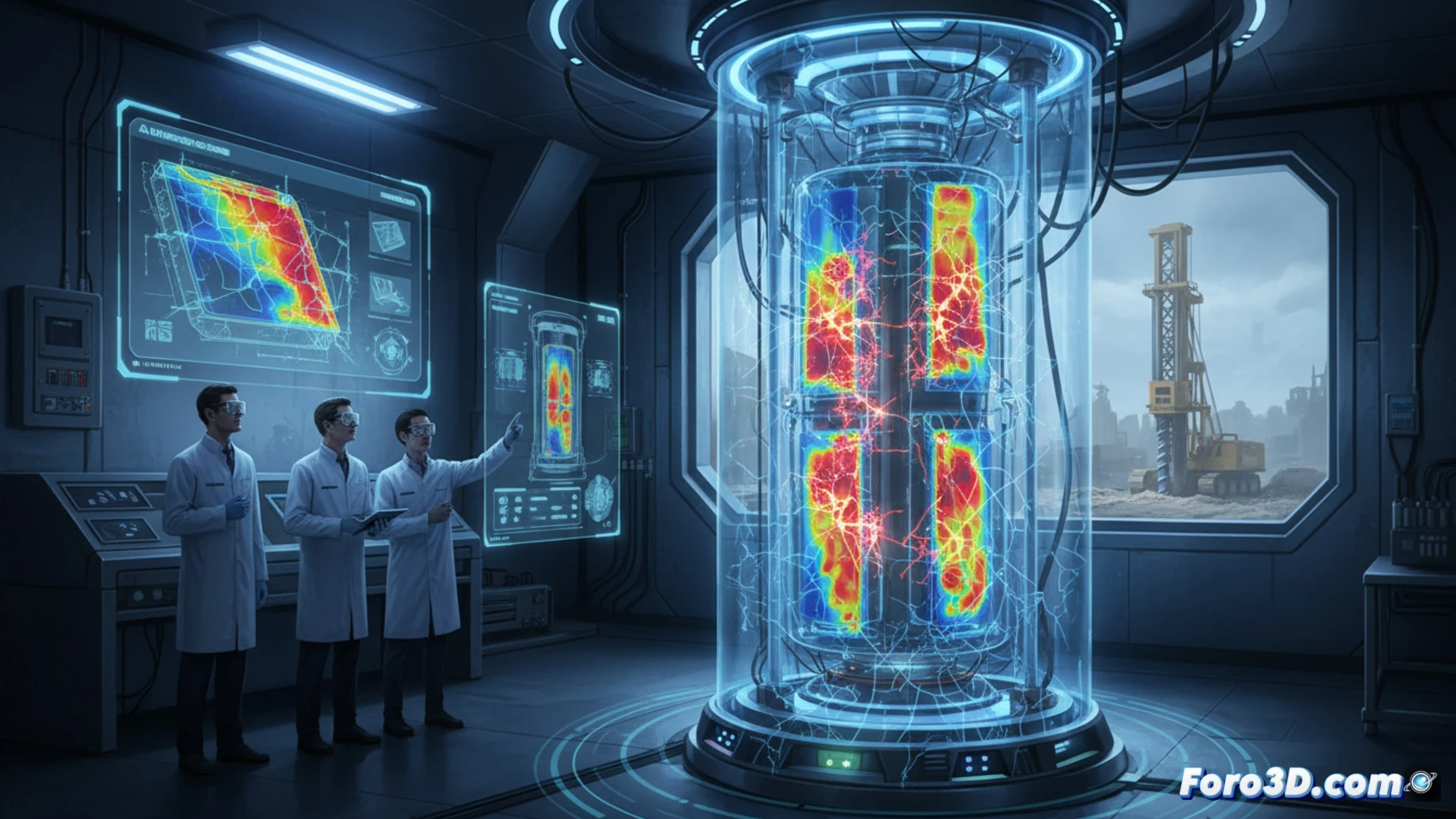
The process began with scanning the panels using Artec Studio to generate a high-density point cloud. In parallel, FLIR Tools 3D was used to fuse thermal data with the surface geometry, identifying areas of greatest heat loss. This data was imported into Revit to model the damaged panel and run a vibration fatigue simulation. The analysis confirmed that the resonant frequencies from the construction site matched the panel's natural frequency, causing cyclic fatigue microfractures, invisible to the naked eye but thermally detectable.
Lessons for Critical Infrastructure Design 🛠️
This incident underscores the need to integrate material fatigue simulation into the design phase of sensitive facilities. The combined use of 3D scanning and thermography not only serves to diagnose failures but also to predict their occurrence. For Foro3D technicians, the lesson is clear: an accurate digital model, fed with environmental vibration data, can prevent silent disasters. Point cloud technology is no longer just for capturing geometry, but for validating the structural integrity of future composite materials.
What advantages does the integration of real-time 3D thermal mapping offer over traditional inspection methods for predicting fatigue failures in cryocoffin panel welds?
(PS: Material fatigue is like yours after 10 hours of simulation.)