Geological hydrogen storage faces a critical challenge: hydrogen-induced embrittlement in salt formations. This phenomenon, known as hydrogen embrittlement, degrades the crystalline structure of halite, causing microcracks and plastic deformations that compromise the integrity of the cavern. In this article, we analyze the technical workflow for simulating structural collapse, integrating parametric modeling, finite element simulation, and validation with point clouds.
Technical Workflow: From Geology to Finite Element Simulation 🛠️
The process begins in AutoCAD Civil 3D, where the cavern geometry is generated from topographic data and stratigraphic profiles. Discontinuities and the typical ellipsoidal shape of leached cavities are modeled. This volume is exported to Respec, specialized geomechanics software. There, the viscoelastic properties of the salt are defined, and a damage model for embrittlement is applied, where hydrogen diffusion reduces fracture energy. The simulation shows the evolution of deformation and cyclic fatigue under operating pressures. To validate the results, Leica Cyclone is used to process 3D laser scans of the real cavern, comparing geometric deviations with model predictions.
Visualizing the Risk: Implications for Energy Infrastructure ⚡
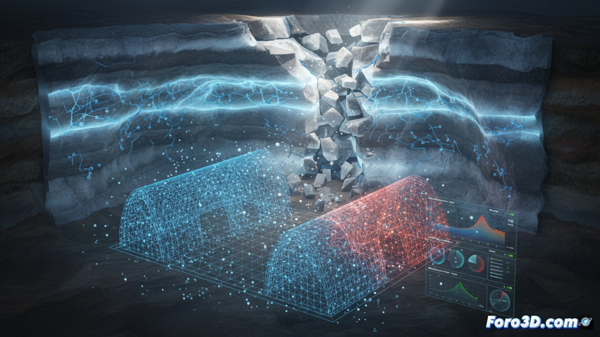
3D visualizations of the degradation process reveal critical stress concentration zones in the roof and side walls. Material fatigue manifests as progressive collapse that, if unmonitored, can lead to catastrophic failure. This integrated approach allows engineers to predict the cavern's service life and design mitigation strategies, such as reducing storage pressure or applying protective coatings. The synergy between numerical simulation and real data is key to the safety of large-scale hydrogen storage.
How can 3D modeling of hydrogen diffusion in the salt microstructure accurately predict critical embrittlement points in geological storage caverns?
(PS: Material fatigue is like yours after 10 hours of simulation.)