The facade of the Aurora Tower, equipped with state-of-the-art electrochromic glass, suffered a catastrophic failure when multiple laminated glass panels fractured without external impact. 3D modeling in Revit and energy simulation in IESVE revealed that the control software generated asymmetric heat gradients on the glass surface. This thermal difference, of up to 45 degrees Celsius between the top and bottom edge of the same panel, caused thermal shock that exceeded the tensile strength of the laminate.
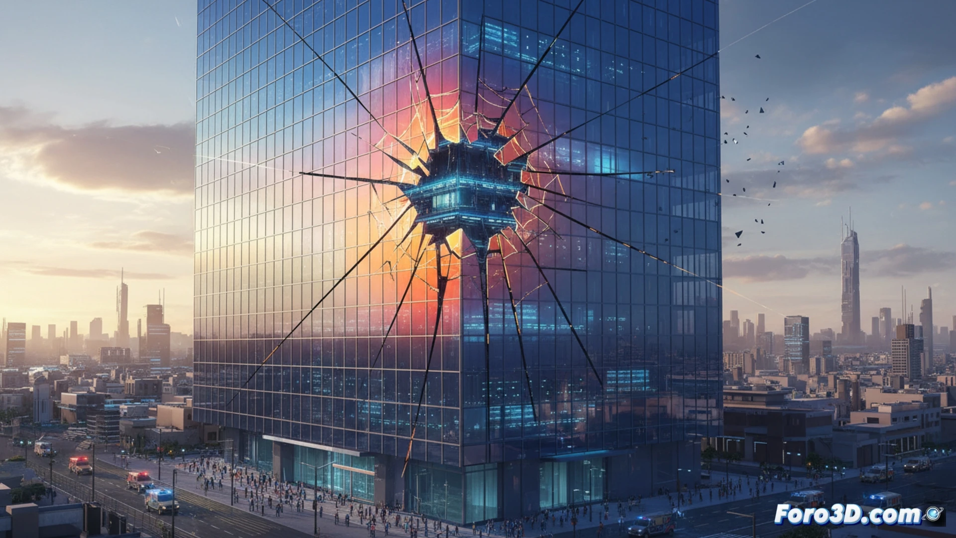
Failure Reconstruction: Asymmetric Gradients and Differential Stresses 🔥
Using Grasshopper for parametric analysis, the behavior of the control system was reproduced. The algorithm, designed to selectively darken areas to reduce glare, activated horizontal strips independently. This created islands of tempered glass adjacent to cold zones. The IESVE simulation showed that the structural joints acted as thermal barriers, preventing heat diffusion. Instead of a smooth gradient, thermal cut lines were generated. The fracture point, located using the finite element model, coincided with the zone of maximum differential stress, where the expansion of hot glass compressed the adjacent cold glass.
Lessons for Fatigue Simulation in Smart Facades ⚙️
This case demonstrates that material fatigue simulation should not be limited to static structural loads. The control software becomes an active agent of thermal stress. To prevent failures, smart facade regulations must include virtual tests where glass activation patterns are simulated. The integration of Revit, IESVE, and Grasshopper allows visualizing these risks before manufacturing. The Aurora fracture was not a glass defect, but a direct consequence of an algorithm that ignored the physics of heat transfer in the laminate.
Considering that the thermal control algorithm prioritized energy efficiency over differential temperature gradients in the electrochromic panels, how could the delay time between electro-tint activation and the actual distribution of thermal stresses be modeled in a finite element simulation to predict the fracture initiation point?
(PS: Material fatigue is like yours after 10 hours of simulation.)