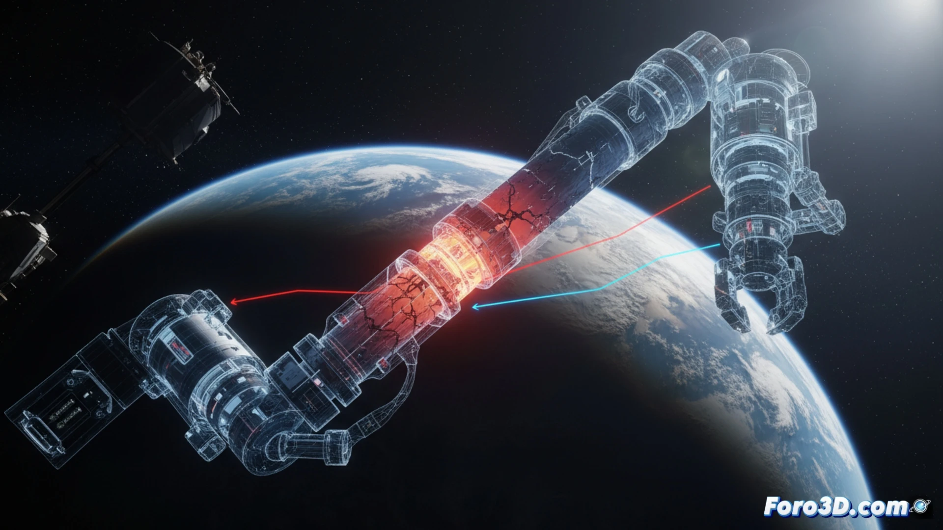
A robotic fuel loading arm on an orbital station failed during docking. The initial investigation pointed to a control error, but 3D modeling revealed a more subtle cause: differential deformation generated by the Earth's shadow. This technical article details how the arm's kinematics were reconstructed in SolidWorks and thermal stress was simulated in Ansys Discovery, identifying critical fatigue points in the actuators that compromised the mission. 🛰️
Kinematic reconstruction and thermostructural analysis in Ansys Discovery 🔥
The first step was to import the arm geometry from Rhino into SolidWorks to parameterize the degrees of freedom of each joint. Orbital boundary conditions were defined: a temperature profile oscillating between 120 degrees Celsius on the illuminated side and -100 degrees in the shadow. In Ansys Discovery, a coupled transient thermal-structural analysis was applied. The results showed that the differential material expansion in the linear actuators generated angular micro-displacements of up to 0.4 degrees, imperceptible on Earth but critical in a vacuum. Cyclic fatigue from these thermal cycles, simulated using the durability module, identified the gimbal joints as the most likely failure point, with a reduced service life of 60 percent under eclipse conditions.
Lessons for preventive simulation in space missions 🛠️
This case demonstrates that material fatigue depends not only on mechanical loads but also on extreme and asymmetric thermal gradients. 3D simulation allowed visualizing the actual arm deformation in KeyShot, facilitating communication of the failure to systems engineers. For future missions, it is recommended to integrate a coupled thermostructural analysis in Ansys from the design phase, validating the kinematics in SolidWorks against shadow cycles. This prevents a temperature change of a few seconds from compromising years of orbital engineering.
As a simulation engineer, when modeling the extreme thermal cycle between the Earth's shadow and direct sunlight on the orbital arm, what meshing parameters and boundary conditions did you consider critical for accurately capturing the onset of a fatigue crack in the articulated joint of the end effector?
(PS: Material fatigue is like yours after 10 hours of simulation.)