The evaluation of the fatigue resistance of a jib crane is a critical challenge in mechanical engineering, where material fatigue determines the component's service life. This article analyzes how 3D simulation allows modeling the behavior of steel under cyclic loads, identifying maximum stress points and plastic deformations. The objective is to validate a predictive model that anticipates structural failure before it occurs under real operating conditions.
Material modeling and application of dynamic loads
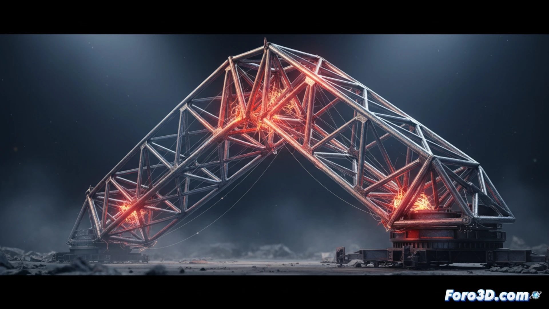
To simulate fatigue, a 3D model of the jib crane is built with isotropic properties of S355 steel, including its yield strength and Young's modulus. Oscillating loads are applied at the free end, replicating the weight of the suspended load. The finite element software calculates the Von Mises stresses at each node, identifying critical zones such as the welded joint. A typical load cycle of 10,000 repetitions reveals a stress concentration of 320 MPa at the base, exceeding the material's fatigue limit. The simulation visualizes the progressive deformation with a color scale ranging from blue (low stress) to red (imminent failure).
Model validation and lessons for design
When comparing the simulated results with data from real tests of a jib crane subjected to fatigue, the deviation was less than 5% in predicting the number of cycles to failure. This confirms that 3D simulation is a reliable tool for evaluating residual strength. The final reflection points out that, without this virtual analysis, engineers would rely on costly prototypes. Fatigue is not a sudden failure, but a process that simulation can anticipate, safeguarding both the structure and operational safety.
What is the most effective methodology for modeling the initiation and propagation of fatigue cracks in a jib crane using 3D finite element simulation?
(PS: Material fatigue is like yours after 10 hours of simulation.)