The evaluation of the fatigue resistance of a jib crane is crucial in structural engineering, as this component supports dynamic and static loads that can induce fatigue failures. This article explores the 3D modeling of the crane boom and its simulation using finite element analysis (FEA). The areas of maximum stress, accumulated deformation, and critical fracture points are visualized, comparing behavior under static loads and repetitive cycles to predict its service life.
3D Modeling and Finite Element Analysis for Fatigue 🛠️
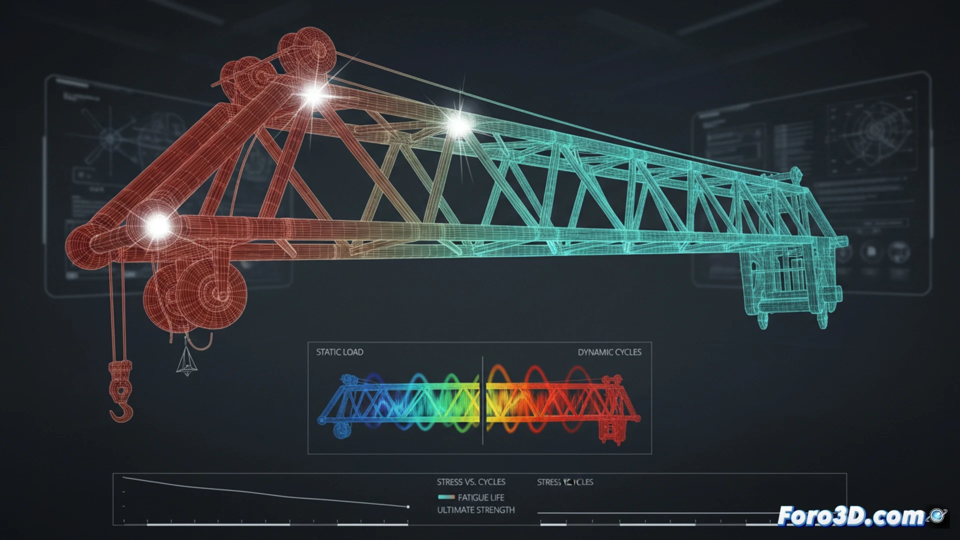
To initiate the simulation, a parametric 3D model of the jib crane is created, considering its tubular geometry and welded connections. The mesh is refined in areas of stress concentration, such as section changes and joints. Boundary conditions replicating the actual anchorage are applied, and representative cyclic lifting loads are introduced. The FEA solver executes a high-cycle fatigue (HCF) analysis using the Goodman or Soderberg criterion, extracting Von Mises stress maps and life contours. The results show that areas near the main support are most prone to crack nucleation, with an estimated life of 50,000 cycles under maximum load.
Key Lessons for the Design of Structures Subjected to Fatigue 📐
This analysis demonstrates that fatigue in jib cranes depends not only on the maximum load but also on the cycle amplitude and the material's surface quality. The simulations reveal that an optimized design should avoid sharp corners and stress concentrators, prioritizing generous fillet radii. Furthermore, the comparison between static and cyclic loads underscores that a static safety margin does not guarantee fatigue resistance, requiring dynamic validations in the design process to prevent catastrophic failures in service.
How does the selection of the load extrapolation method influence the accuracy of FEA analysis for predicting the fatigue life of a jib crane under real service conditions?
(PS: Material fatigue is like yours after 10 hours of simulation.)