The fragmentation of a pneumatic tank is not a random event, but the culmination of a predictable mechanical process. When a pressurized container fails, the accumulated energy is violently released. This article analyzes how finite element simulations (FEM) allow us to visualize the path of rupture, from the initial microcrack to catastrophic fragmentation, explaining the mechanisms of cyclic fatigue and overpressure that govern the failure.
Technical Analysis: Microcracks, Propagation, and Stress Distribution 🔧
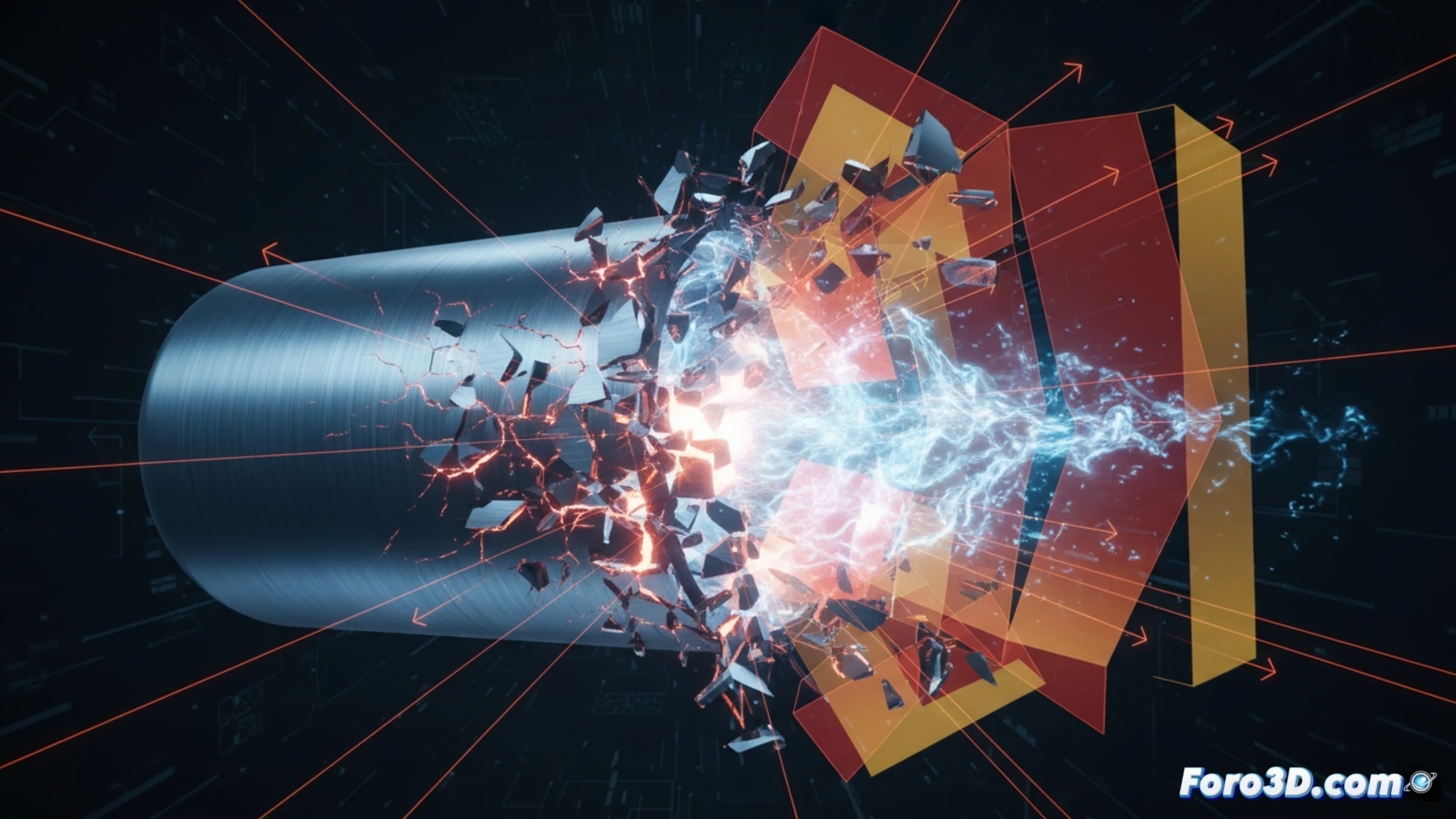
In the context of material fatigue, a pneumatic tank undergoes pressure cycles that generate localized stresses, especially in welds and cross-section changes. 3D simulations reveal how these stresses exceed the elastic limit of steel or aluminum, initiating microcracks. Using fracture mechanics models, such as the Paris criterion, we can animate crack propagation. The FEM mesh shows stress hot spots (stress concentrators) that act as triggers. When the crack reaches a critical size, internal pressure causes a brittle or ductile fracture, fragmenting the tank into multiple shards. Animations of this process are crucial for understanding the dynamics of explosive decompression.
The Visual Lesson of Controlled Failure 🎯
Beyond the numbers, 3D simulation offers an invaluable visual lesson. Seeing how the crack snakes through the material, deviating due to inclusions or weak zones, humanizes fatigue theory. This analysis not only prevents accidents but also redefines design standards. A fragmented tank is a failure, but its simulation is a safety tool. By studying these fracture patterns, engineers learn to predict disaster before it occurs, optimizing thicknesses and heat treatments to extend the system's lifespan.
What critical parameters of the 3D simulation allow for accurately predicting the initiation point and trajectory of fragmentation in pneumatic tanks subjected to cyclic fatigue?
(PS: Material fatigue is like yours after 10 hours of simulation.)