A gas leak in a climate control network is not just a technical failure; it is the prelude to a potential catastrophe. The accumulation of liquefied gas or refrigerant in confined spaces can generate explosive atmospheres or mass poisonings. For prevention professionals, understanding the dynamics of this leak is critical, and 3D modeling emerges as the most precise tool to anticipate disaster before it occurs.
Digital twins for dispersion simulation 💨
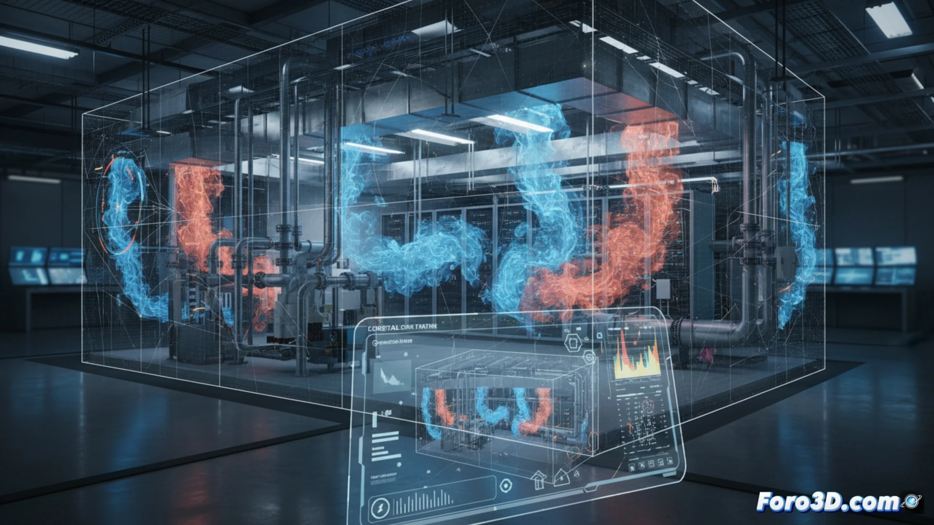
The technical process begins with the creation of a digital twin of the installation. Each pipe, valve, and diffuser is modeled, assigning physical properties such as pressure, flow rate, and gas type. Using computational fluid dynamics (CFD) software, the drift is simulated under failure conditions. The model allows visualizing how the gas moves through false ceilings, ducts, and grilles, identifying stagnation zones where the concentration reaches the lower explosive limit (LEL). This 3D analysis reveals blind spots that 2D plans hide.
Visual prevention of risk scenarios 🛡️
The true utility of the 3D model lies in its ability to test scenarios. The activation of a detector, the closure of a valve, or the evacuation of personnel can be simulated. By visualizing the temporal evolution of the gas cloud, engineers design more effective safety protocols, and firefighters plan safe access routes. This approach transforms an abstract accident into a manageable virtual reality, saving lives by turning prediction into prevention.
As a 3D modeler, what gas dispersion simulation metrics do you consider essential for predicting the formation of lethal pockets in HVAC ducts before an explosion occurs?
(PS: Simulating catastrophes is fun until the computer crashes and you are the catastrophe.)