The incident of the autonomous bus that fled out of control raises critical questions about the reliability of autonomous driving systems. From a technical perspective, this event is not a simple accident, but a window into the vulnerabilities in the architecture of autonomous vehicles. We will analyze the case by 3D modeling the escape route to visualize the decisions of the electronic control unit (ECU) and sensor data.
3D Visualization of the Electrical Architecture and ECU Failure 🚌
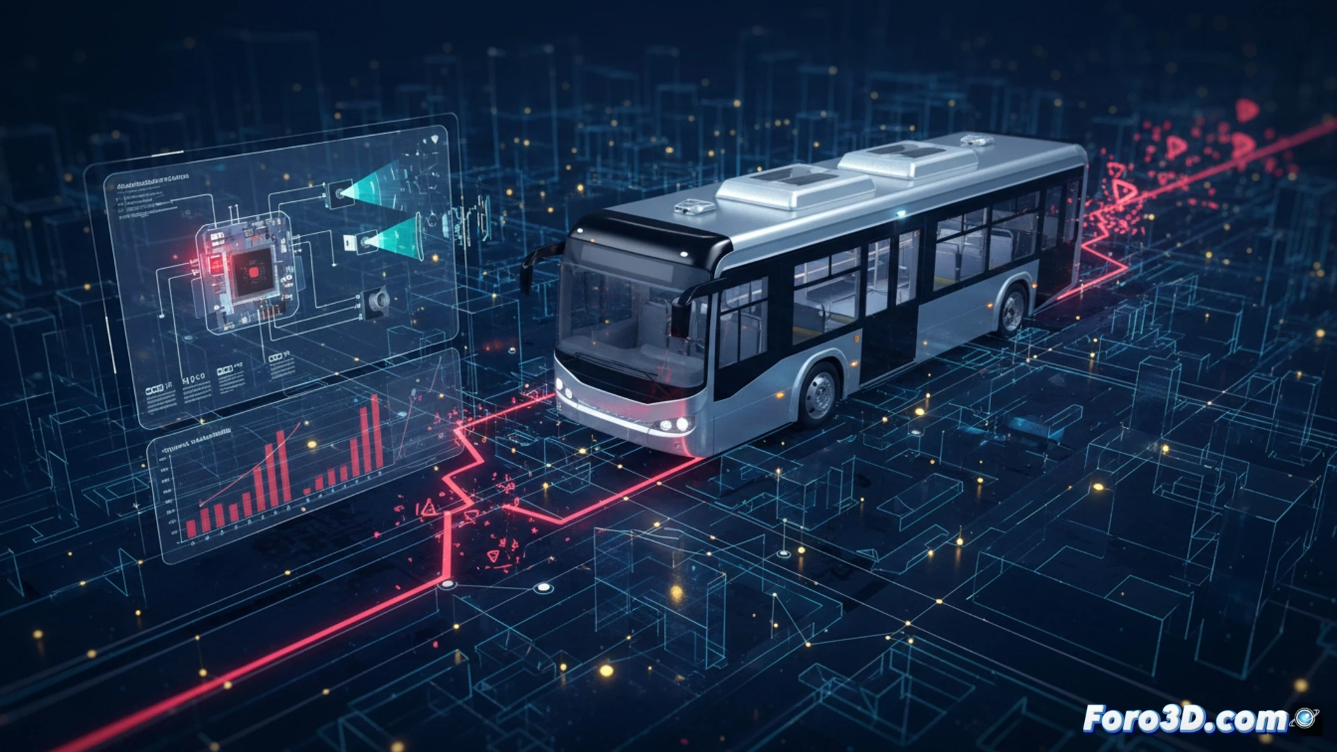
To understand the failure, we modeled the bus and its control system in 3D, breaking down the hierarchy of the main ECU and peripheral units. The simulation reveals a disconnection between the accelerator position sensor and the traction control module. In the 3D recreation, it is observed how the bus ignored emergency braking signals because the CAN (Controller Area Network) bus prioritized an erroneous command from a faulty speed sensor. This visual analysis allows engineers to identify the exact point of failure in the control loop, which could be due to a short circuit or an error in the accelerator actuator firmware.
Lessons for Embedded System Design in Autonomous Vehicles ⚙️
The bus escape demonstrates that sensor redundancy is not sufficient if the ECU's decision logic is not properly isolated. The improvement proposal, viewable in our 3D model, is to implement a triple modular redundancy (TMR) control architecture in the power management unit. This would prevent a single corrupt sensor, like the one we simulated, from overriding safety commands. 3D modeling not only documents the incident but becomes an essential tool for redesigning embedded systems and preventing future autonomous escapes.
How can 3D modeling of the route and failure geometry analysis of ADAS sensors help predict and prevent uncontrolled escapes in autonomous buses during critical maneuvers?
(PS: simulating an ECU is like programming a toaster: it seems easy until you order a croissant)