The recent news about the fracture of a micro-turbine in service has focused attention on material fatigue as the main cause of the failure. These types of components, subjected to extreme stress cycles in confined spaces, develop microcracks that progress to catastrophic rupture. In this article, we will analyze how 3D simulation allows us to visualize the phenomenon, identifying critical points of stress concentration and crack evolution.
Technical Analysis: Stress Maps and Crack Progression 🔍
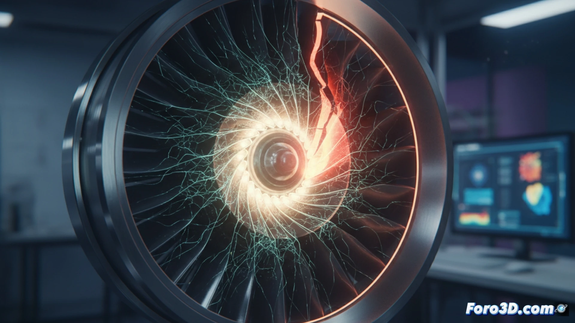
Using finite element models (FEM) applied to the actual geometry of the micro-turbine, we can generate stress maps that reveal areas of high cyclic stress, typically at the blade root and notch radii. The 3D simulation shows how repetitive loading generates localized plastic deformation, initiating a crack that advances following the direction of maximum principal stress. By visualizing the failure progression in the three-dimensional model, engineers can observe the exact nucleation point and propagation speed, critical data for adjusting the component's service life limits.
Design Lessons: Predict to Prevent 🛠️
Beyond forensic analysis, 3D fatigue simulation offers a vital predictive tool. By recreating load conditions and operating cycles in a virtual environment, we can identify design weaknesses before manufacturing. This allows modifying curvature radii, selecting alloys with better fatigue resistance, or implementing surface treatments such as shot peening. The fracture of this micro-turbine is not just a failure case, but a reminder that 3D modeling is the key to extending the life of critical components.
How to implement in 3D simulation the effects of fatigue-induced microcracks in high-strength alloys to accurately predict the service life of a micro-turbine before its catastrophic fracture in service?
(PS: Material fatigue is like yours after 10 hours of simulation.)