Compressor failure is not a random event; it is the culmination of microcracks growing under cyclic loads until structural integrity is compromised. Material fatigue analysis has become the central tool for understanding these failures, allowing engineers to predict the exact fracture point in blades and rotors. 3D technology, through finite element models (FEM), offers a direct window into material behavior.
Finite Element Modeling for Fracture Analysis in Blades 🔧
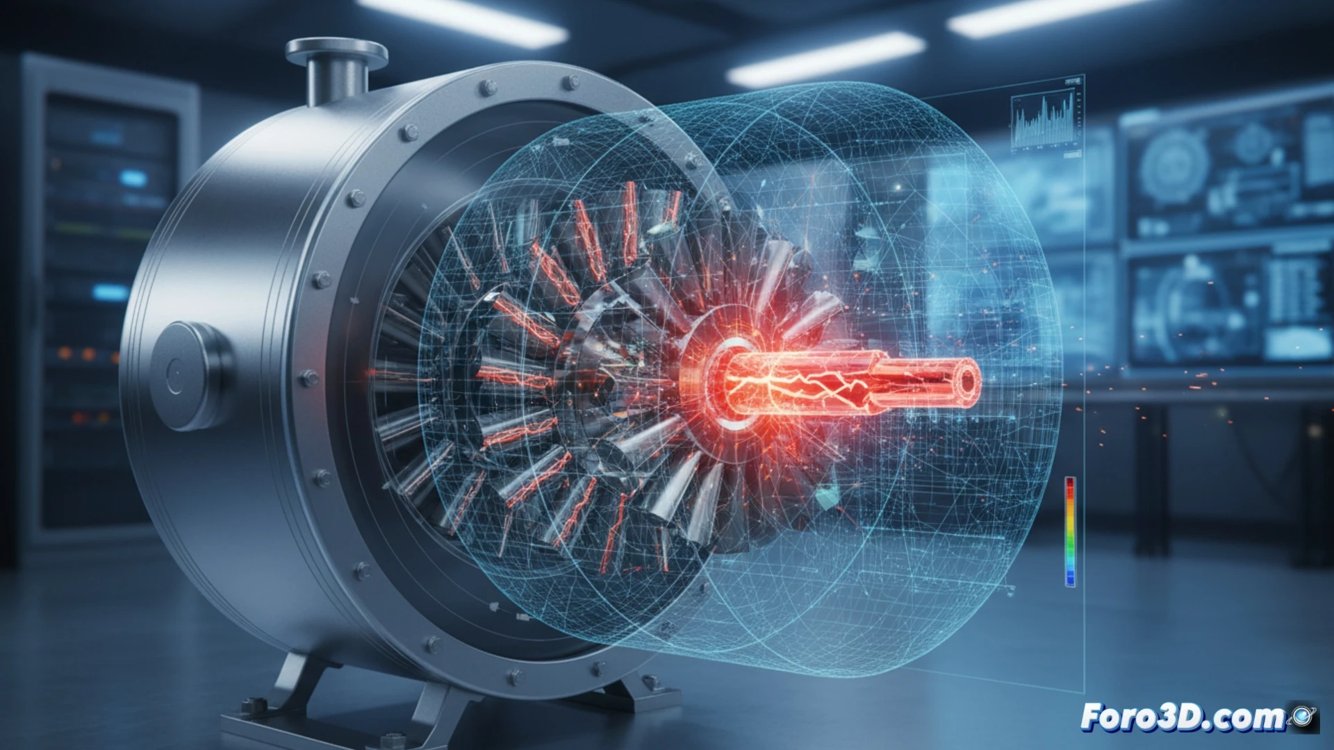
A practical case illustrates the process: a Ti-6Al-4V titanium compressor blade presents a transverse fracture near the leading edge. A 3D model is built, meshed with high-resolution hexahedral elements in the critical zone. The simulation applies a cyclic load of 500 MPa with a stress ratio R=0.1, representing 10 million operating cycles. The FEM analysis reveals a stress concentration at the blade fillet radius, with a value of 780 MPa, exceeding the material's fatigue limit. The 3D visualization of the plastic strain distribution precisely locates the crack initiation, coinciding with the documented location of the actual field failure.
The Technical Lesson Behind the Failure ⚙️
The agreement between the 3D model and the actual failure confirms that fatigue simulation is not just a predictive tool, but a mirror of physical reality. For the simulation engineer, this exercise demonstrates that mesh density and correct definition of boundary conditions are critical. Ignoring material behavior under cyclic loading in 3D design is inviting catastrophic failure; understanding it is the foundation of reliability engineering.
How would you model in a 3D environment the propagation of microcracks in compressor blades under cyclic loads to predict the exact point of critical failure before it occurs under real operating conditions?
(PS: Material fatigue is like yours after 10 hours of simulation.)