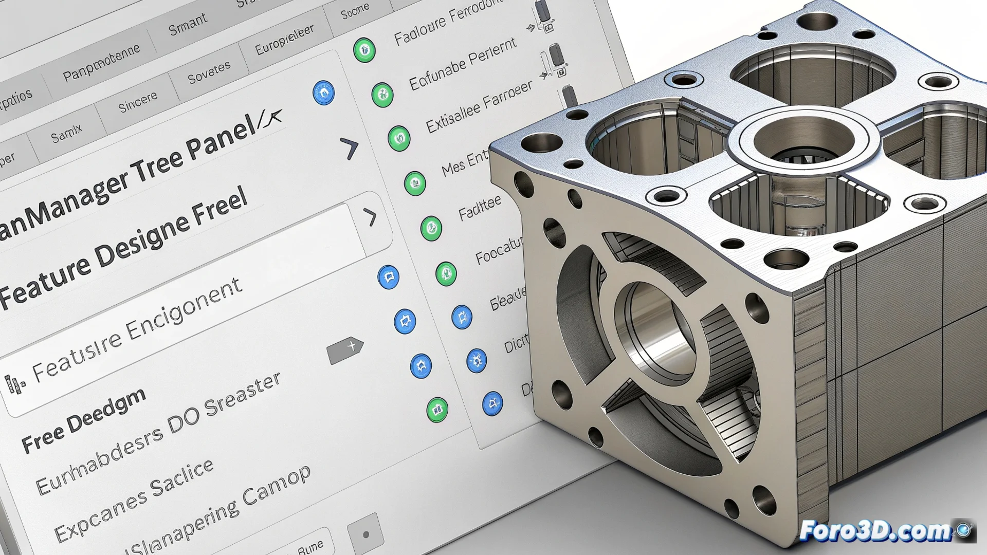
The FeatureManager Design Tree in SolidWorks: Modeling Control Center
In the SolidWorks environment, the panel known as the FeatureManager Design Tree acts as the central core for managing any 3D model. This design tree lists sequentially every action a user performs, from the first sketches to complex detailing operations, providing a complete map of the creative process. Its presence is essential for maintaining absolute control over the project. 🗂️
Modify the design without losing previous work
The ability to edit non-destructively is the main strength of this tool. Instead of deleting and redoing, you can select any feature in the list and adjust its parameters directly. Changing the dimensions of a cut or the angle of a chamfer becomes an instantaneous process. Additionally, dragging elements within the tree to alter their construction order allows you to explore different results without compromising the model's base. This flexibility accelerates the design cycle and encourages experimentation.
Key actions you can perform:- Edit parameters: Double-click on any operation to modify its values, such as the length of an extrusion or the diameter of a hole.
- Reorder features: Drag and drop elements to change the sequence in which the part is built, which can significantly alter its final geometry.
- Suppress operations: Remove a feature from the history; the model regenerates automatically without it, as long as the geometric references of subsequent operations remain valid.
The FeatureManager Design Tree is not just a list; it is the living history of your model. Managing it well is the key to stable and easy-to-modify design.
Understanding the organization and elements of the tree
This panel goes beyond listing cuts and protrusions. It integrates all the components that define a model, including reference planes, custom coordinate systems, assigned materials, and visual appearances. Elements are nested logically; for example, all operations derived from a specific sketch are grouped under it. Icons adjacent to each item function as traffic lights: green for correct operations, yellow for warnings, and red for errors that require immediate attention. This visualization helps diagnose conflicts and understand dependencies between features.
Common components you will find:- Base modeling operations: Extrusions, revolutions, cuts, fillets, and chamfers.
- Reference elements: Planes, axes, points, and user-defined coordinate systems.
- Properties and appearances: Applied materials, textures, and model-specific configurations.
Avoid and resolve common problems
A frequent error is deleting a base operation on which subsequent features depend. This causes a cascade of failures, filling the tree with red icons indicating broken references. To avoid it, it is crucial to plan the order of operations and use stable geometric references, such as reference planes or original geometries. Regularly reviewing the tree allows you to detect these warnings in time and correct them by redefining lost references, thus ensuring the robustness and stability of the entire 3D design. 🔧