When German Engineering Challenges Gravity
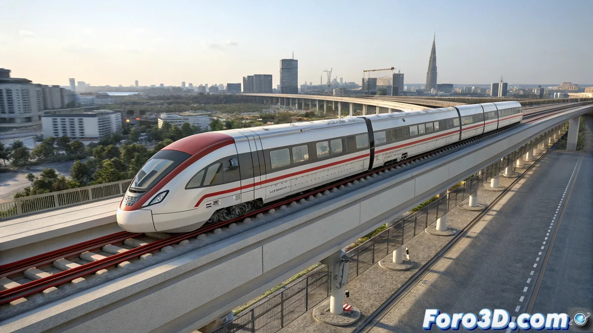
Germany continues to innovate in transportation with Max Bögl's TSB magnetic levitation system, designed to revolutionize urban and periurban journeys. 🚄✨ In SolidWorks, we can capture this advanced technology, modeling not only the train's aesthetics but also the engineering principles that enable its contactless operation on the tracks. This technical representation shows how magnetism and aerodynamic design combine to create efficient and sustainable transportation.
Initial Setup of the Parametric Model
Upon starting SolidWorks, a new part file is created by setting units to millimeters for precision in small components. FeatureManager organization is crucial: Chassis, Levitation_System, Body, and Tracks must be structured hierarchically. Saving as tren_maglev_tsb.sldprt ensures all parameters are preserved… because in magnetic engineering, as in 3D modeling, every millimeter counts.
Chassis and Aerodynamic Body Design
The train's aerodynamic profile is created using spline sketches that define the cross-section, extruded along a curved path. 🌀 The cabin and cars are modeled as continuous surfaces with smooth transitions to minimize air resistance, reflecting the focus on energy efficiency. Materials are assigned as aluminum for the structure and composites for exterior elements, using realistic appearances while maintaining visual clarity.
3D modeling of transportation systems does not only replicate shapes; it allows analyzing complex physical interactions such as magnetic forces, airflow, and motion dynamics in controlled virtual environments.
Levitation and Propulsion System
The magnetic components are modeled as arrays of permanent magnets and electromagnets under the chassis. 🧲 Section cuts are used to reveal the internal arrangement and alignment with the coils on the track. The linear propulsion system is represented by stator coils on the track and reactor components on the train, using differentiated colors for clarity. This technical layer showcases the invisible engineering that makes levitation possible.
Visualization and Analysis Techniques
- Exploded Views: Controlled assemblies are created to show the spatial relationship between levitation, propulsion, and structure systems.
- Force Simulation: Analysis tools are used to visualize magnetic fields and lift forces, represented by color maps.
- Travel Animations: Trajectories along curved tracks are programmed to demonstrate stability and curve negotiation capability.
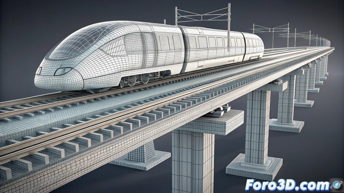
Rendering and Technical Documentation
Technical renders are configured with wireframe style over a neutral background, highlighting engineering details. 📐 Views are complemented with dimensions and annotations specifying critical dimensions—such as levitation distance and magnet spacing. This visual documentation serves both educational purposes and design concept validation.
Beyond Visualization
This model allows exploring design variants—different magnetic configurations, aerodynamic optimizations, or adaptations to various urban environments. 🏙️ SolidWorks' parametric nature facilitates rapid iteration over concepts, testing alternatives without physical prototyping costs.
Thus, while German engineers perfect real levitation, we can experiment with magnetic principles in a virtual space… where the only limiting force is imagination. Because in SolidWorks, even gravity is optional. 😉