Lines, Circles, and Construction Points in QCAD: Essential Guides
In the 2D technical drawing environment, construction entities in QCAD act as the invisible skeleton of a project. They are fundamental auxiliary tools that, although they are not printed or part of the final result, allow defining and constraining the geometry with absolute precision. Working without them is like trying to build without a reference plan. 🏗️
What These Temporary Entities Are Used For
Their main function is to serve as infinite or temporary geometric guides. They allow aligning other elements, finding centers, defining tangents, and projecting symmetries. A well-organized and logical technical drawing almost always relies on a network of these guides, which are then hidden or deleted.
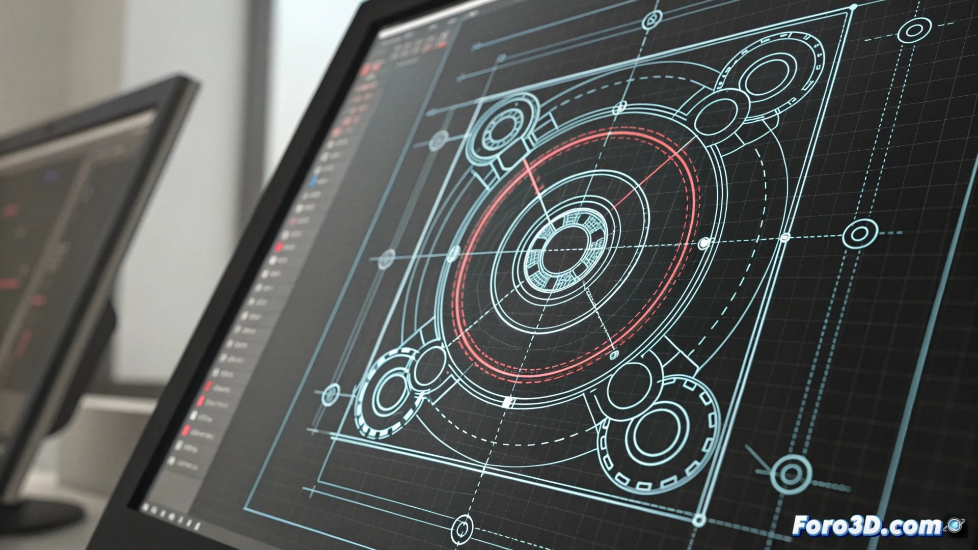
Key Features of Construction Guides:- Distinct Visual Style: They are displayed with a dashed stroke or a different color (like cyan) to distinguish them from definitive lines.
- Flexible Behavior: They can be drawn, edited, moved, and deleted just like any other entity in QCAD.
- Layer Management: It is optimal practice to draw them on a dedicated layer, which makes it easy to lock them or make them invisible when finished.
Technical precision often hides behind a tangle of guides that are later deleted. A drawing without construction lines may look cleaner, but building without scaffolding is risky.
How to Create and Control the Guides
The process to generate them is straightforward. From the Draw menu or via its icon in the toolbar, the option for Construction Line, Construction Circle, or Construction Point is activated. Their stroke is identical to that of normal entities, but their appearance immediately reveals them as auxiliaries.
Recommended Workflow:- Activate the specific tool from the menu or toolbar.
- Draw the necessary guides to define axes, centers, or limits.
- Use a separate layer called "Construction" or "Guides" to group all these entities.
- Draw the final geometry (lines, arcs, dimensions) using the guides as reference.
- Hide or lock the construction layer when presenting or printing the drawing.
Applying These Guides in a Real Project
Imagine drawing the front view of a mechanical part. First, construction lines are drawn to mark the horizontal and vertical symmetry axes. Then, with construction circles, the radii and the position of the holes are defined. These guides help position each contour and detail symmetrically and precisely. Finally, over this auxiliary scheme, the definitive lines that make up the part are drawn. This method not only organizes the workspace, but also ensures that future modifications can be made coherently and controlled. ✅