How to Model Corridors in Autodesk Civil 3D for Linear Infrastructures
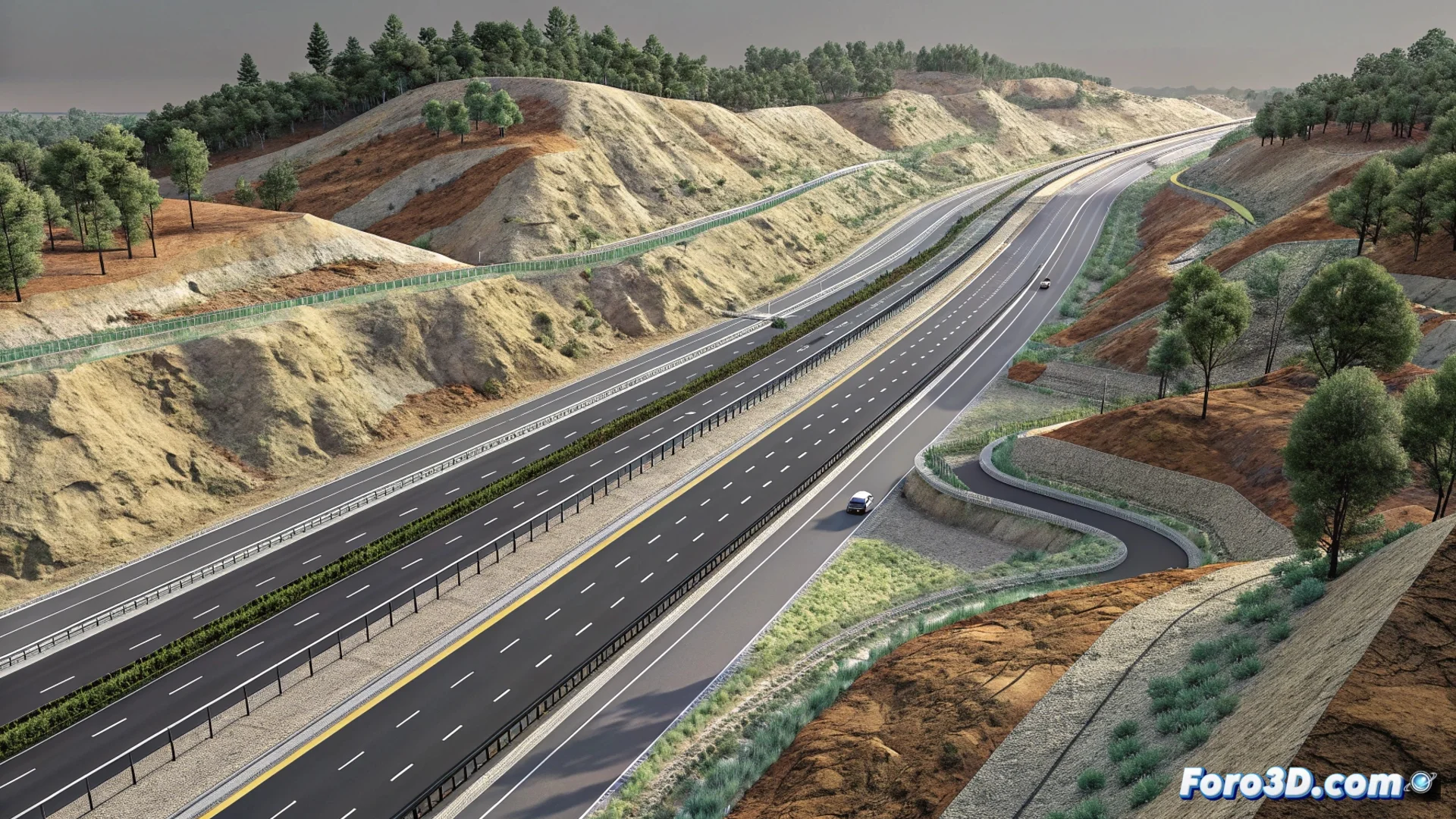
In the field of civil engineering design, Autodesk Civil 3D offers a key function to project linear infrastructures such as railways, roads, or irrigation channels. This tool, known as Corridors, automates the process of creating the complex three-dimensional geometry that these projects require, saving time and reducing errors. 🛣️
The Three Fundamental Pillars of the Corridor
To build a corridor model, the software synthesizes three essential data components. First, a horizontal alignment that traces the route of the axis in plan. Second, a vertical profile associated with that axis, which defines the slopes and grades. The third and crucial element is the assembly, a template of the cross-section that includes subassemblies such as the roadway, slopes, or ditches. Civil 3D processes this data along the entire alignment to generate a solid and continuous model that adapts to the existing terrain.
Elements that configure a typical assembly:- Sidewalk and roadway: Defines the main platform of the infrastructure.
- Slopes and berms: Controls the transition between the platform and the natural terrain.
- Ditches and drainage systems: Manages the evacuation of surface water.
The corridor acts as a central dynamic model; any change in the alignment, profile, or assembly automatically propagates throughout the design.
Workflow to Generate the 3D Model
The user starts the process by defining the project route with the alignment. Subsequently, assigns the elevation profile. The power of the system is unleashed by inserting the predefined assembly at established intervals along the axis. The program intelligently calculates how each cross-section intersects with the terrain surface, assembling the complete three-dimensional model. This updates in real time if any of its constituent parts is modified.
Data and products extracted from the corridor:- Final project surfaces: Digital models of the terrain resulting from the design.
- Volume calculations: Accurate earthwork volumes between surfaces.
- Sampling lines: Detailed cross-sections at specific points.
Advantages in Documentation and Productivity
Once generated, the corridor becomes the single source of truth for the project. It allows producing plan, profile, and section drawings automatically, ensuring absolute consistency throughout the documentation. Although configuring a complex assembly for the first time may seem challenging, the efficiency gained in the design, calculation, and drawing generation phases more than compensates for that initial effort. 🚀