An accident at over 280 km/h in the last Grand Prix left the team with a doubt that transcended the mechanical. Initial visual inspections detected nothing anomalous, but telemetry data indicated a sudden loss of aerodynamic downforce in the high-speed corner. Suspicion of sabotage arose when the chief engineer noticed that the fracture of the rear wing did not match the usual fatigue patterns. Something microscopic had been altered.
Industrial scanning and forensic analysis with GOM ATOS 🔬
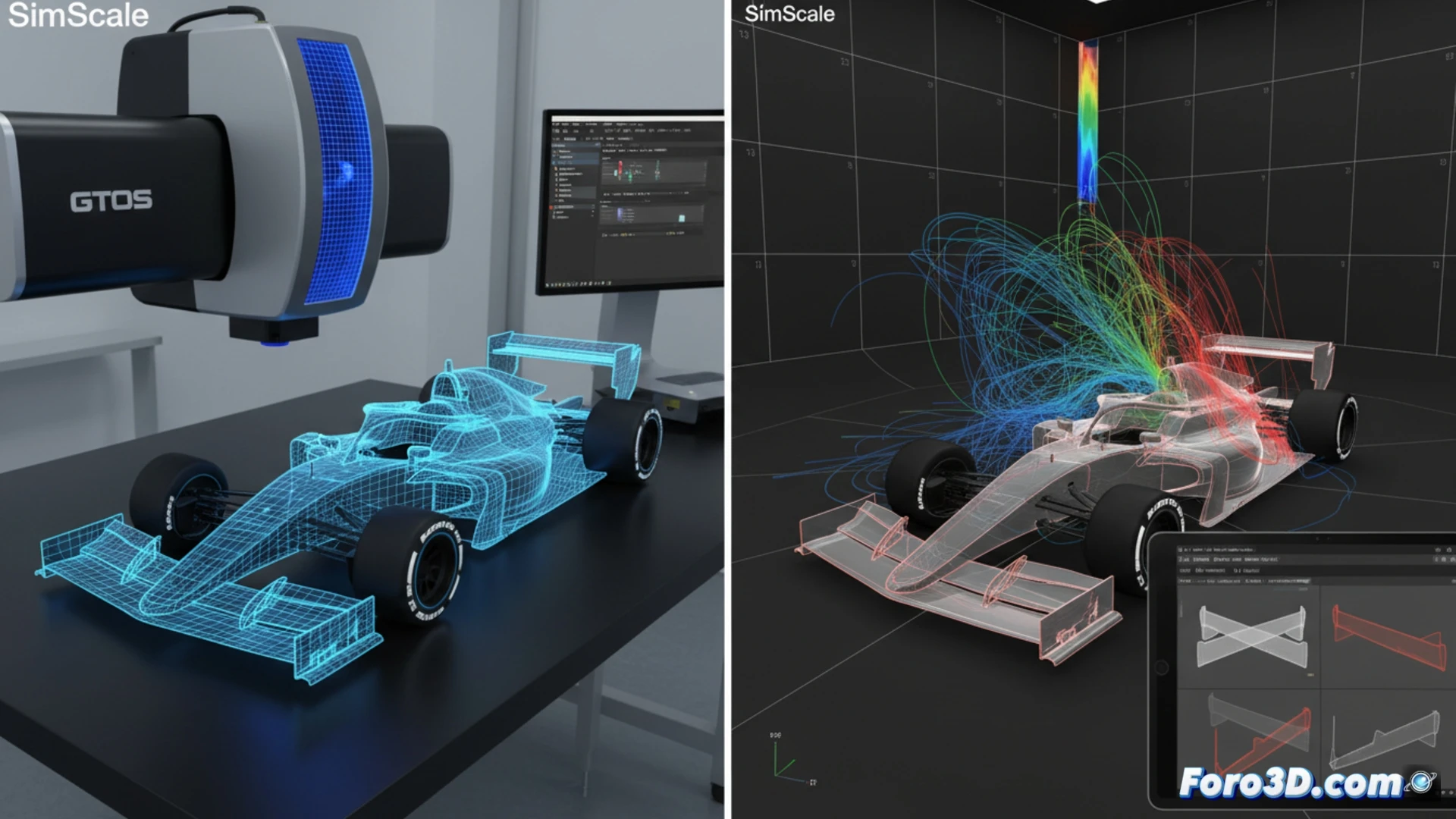
To solve the mystery, the forensic team turned to the GOM ATOS industrial scanner, capable of capturing millions of points with micrometric precision. The fractured component was digitized in 3D and the resulting point cloud was imported into Geomagic Control X. There it was superimposed with the team's original CAD design. The comparison revealed an imperceptible deviation to the naked eye: a reduction of just 0.15 millimeters in the radius of curvature of the wing's leading edge. This modification, carried out with precision tools, altered the aerodynamic profile right in the critical high-pressure zone. The software generated a color map showing the altered area in intense red, while the rest of the component remained green, within tolerance.
CFD Simulation: The virtual condemnation of sabotage 💨
With the real geometry already captured, a CFD simulation was executed in SimScale and Ansys Discovery. Two models were compared: the original design and the sabotaged part. The results were devastating. In the altered model, the airflow detached prematurely from the leading edge, generating a turbulent wake that reduced downforce by 23% at 280 km/h. The streamlines showed an unstable vortex exactly where the wing was supposed to bear the greatest stress. The coupled structural analysis confirmed that this pressure loss generated high-frequency vibrations that exceeded the material's fatigue limit, causing the catastrophic fracture. The evidence was clear: it was not a failure, it was an aerodynamic sabotage calculated to the micrometer.
What is the allowable margin of error in the design and manufacturing of critical F1 components via 3D printing, and how can structural integrity be guaranteed against variations of one micron?
(PS: simulating an ECU is like programming a toaster: it seems easy until you order a croissant)